How to Configure the Switch to Tunnel Layer 2 Protocol Packets Through Service Provider Network

 Zyxel Employee


Zyxel switch models support Layer-2 Protocol Tunneling (L2PT) that allows edge switches to tunnel layer-2 protocol packets through service provider networks. It could be used when customer switches are located at different sites and connected across a service provider network.
Therefore, the customer networks can implement independent layer 2 protocol solutions. For example, it could provide a single and independent spanning tree domain for customer networks across a service provider network.

When Edge switch-1 receives Layer-2 protocol packets, it will encapsulate these packets and rewrite their destination MAC addresses with a specific MAC address. All the switches inside the service provider network treat these encapsulated packets as data packets and forward them to the other side. When Edge switch-2 receives these encapsulated packets, it will decapsulate them and change their destination MAC addresses back to the original one before forwarding them to the destination switch.
Each port on edge switch has two modes:
- Access Port: For ingress ports which reside on the service provider's edge switch and connect to a customer switch, incoming layer 2 protocol packets received on an access port are encapsulated and forwarded to the tunnel ports.
- Tunnel Port: For egress ports which reside on the edge of the service provider's network and connect to another service provider’s switch, incoming encapsulated layer 2 protocol packets received on a tunnel port are decapsulated and sent to an access port.
The following example will instruct how an administrator configures a switch to tunnel STP packets through a service provider network.

Note:
The example was tested using two XGS4600 as edge switches, and two GS2210 as customer switches.
1.Configuration on the Edge Switch
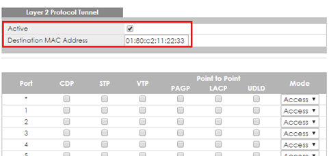
1-1. Setup Edge Switch-1: Access to the web GUI. Go to Advanced Application > Layer 2 Protocol Tunneling. Check “Active”, and set the “Destination MAC Address”.
Note:
Destination MAC Address can be either a unicast MAC address or a multicast MAC address:
- For unicast MAC address: make sure the MAC address does NOT exist in the MAC table of switches which reside in the service provider’s network.
- For multicast MAC address: make sure the MAC address is NOT used for specific protocols, such as STP, VTP, ….
Note:
All the edge switches in the service provider’s network should use the same MAC address for encapsulation.
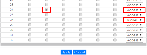
1-2. Setup Edge Switch-1: On the same page. Check “STP” and set “Mode” as “Access” on port 26 which connects to the customer switch.
1-3. Setup Edge Switch-1: On the same page. Set “Mode” as “Tunnel” on port 28 which connects to another edge switch in service provider’s network, and click “Apply”.


Note:
Activate L2PT services for supported protocols on the access port(s) only.
1-4. Setup Edge Switch-2: Access to the web GUI. Go to Advanced Application > Layer 2 Protocol Tunneling. Activate Layer 2 Protocol Tunnel, and set the “Destination MAC Address”.

Note:
Destination MAC Address can be either a unicast MAC address or multicast MAC address:
- For unicast MAC address: make sure the MAC address does NOT exist in the MAC table of switches which reside in the service provider’s network.
- For multicast MAC address: make sure the MAC address is NOT used for specific protocols, such as STP, VTP, ….
Note:
All the edge switches in the service provider’s network should use the same MAC address for encapsulation.
1-5. Setup Edge Switch-2: On the same page. Activate STP and set mode as “Access” on port 26 which connects to the customer switch.
1-6. Setup Edge Switch-2: On the same page. Set mode as “Tunnel” on port 28 which connects to another edge switch in service provider’s network, and click “Apply”.

Note:
Activate L2PT services for supported protocols on the access port(s) only.
2.Configuration on the Customer Switch
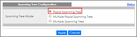
2-1. Setup Customer Switch-A: Access to the Web GUI. Go to Menu > Advanced Application > Spanning Tree Protocol > Configuration. Check if the Spanning Tree Configuration is Rapid Spanning Tree. If not, select it and click “Apply”.

Note:
It is not necessary to enable STP on edge switches because edge switches only forwarding STP packets through tunnel.
2-2. Set up Customer Switch-A: Enter the web GUI. Go to Menu > Advanced Application > Spanning Tree Protocol > RSTP. Check the “Active” box, and set the Bridge Priority = 4096. Activate port 10, and click “Apply”.

2-3. Setup Customer Switch-B: Access to the Web GUI. Go to Menu > Advanced Application > Spanning Tree Protocol > Configuration. Check if the Spanning Tree Configuration is Rapid Spanning Tree. If not, select it and click “Apply”.
2-4. Set up Customer Switch-B: Enter the web GUI. Go to Menu > Advanced Application > Spanning Tree Protocol > RSTP. Check the “Active” box. Activate port 10, and click “Apply”.

3.Test the Results
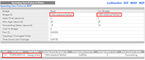
3-1. Verify the status of Customer Switch-A: Go to Menu > Advanced Application > Spanning Tree Protocol. The Root Bridge ID and the Our Bridge ID should be the same. This means that Customer Switch-A is the Root Bridge. Port 10 should be in FORWARDING state, and its Port Role is Designated Ports.
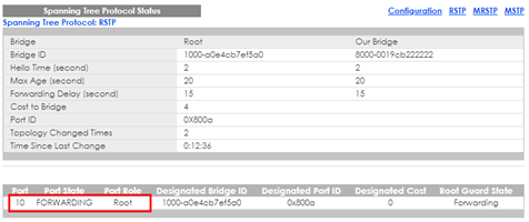
3-2. Verify the status of Customer Switch-B: Go to Menu > Advanced Application > Spanning Tree Protocol. Check the port status of Customer Switch-A. Port 10 should be the Root Port in FORWARDING state.
4.What Could Go Wrong
Make sure you configure the same destination MAC address of Layer-2 Protocol Tunneling on all the edge switches. Otherwise the encapsulated packets cannot be recognized during the forwarding process between the edge switches.
Categories
- All Categories
- 384 Beta Program
- 2.1K Nebula
- 117 Nebula Ideas
- 80 Nebula Status and Incidents
- 5.1K Security
- 79 USG FLEX H Series
- 247 Security Ideas
- 1.3K Switch
- 69 Switch Ideas
- 909 WirelessLAN
- 34 WLAN Ideas
- 5.9K Consumer Product
- 209 Service & License
- 335 News and Release
- 71 Security Advisories
- 21 Education Center
- 5 [Campaign] Zyxel Network Detective
- 1.9K FAQ
- 898 Nebula FAQ
- 415 Security FAQ
- 234 Switch FAQ
- 205 WirelessLAN FAQ
- 46 Consumer Product FAQ
- 137 Service & License FAQ
- 34 Documents
- 34 Nebula Monthly Express
- 73 About Community
- 62 Security Highlight