GRE over IPSec VPN Tunnel –VPN Failover

 Zyxel Employee


Application scenario
We want to use VPN tunnels to transfer important files between the
branch Office and HQ. To prevent the network from getting
disconnected , we configure four WAN interfaces to do redundancy.
Now, we want to establish two VPN tunnels between the two USGs to
perform failover, to ensure that the transfer will not be interrupted when
the fi rst connection encounters a problem. This will create a stable
environment for the transfer.

Configuration Guide
Network conditions:
USG1
WAN1 IP: 192.168.1.33
WAN2 IP: 192.168.2.33
GRE tunnel interface1:10.0.0.1
GRE tunnel interface2:10.10.0.2
USG2
WAN1 IP: 192.168.3.33
WAN2 IP: 192.168.4.33
GRE tunnel interface1:10.0.0.3
GRE tunnel interface2:10.10.0.4
Goals to achieve:
Use GRE over IPSec VPN to perform the VPN fail over.
USG configuration
Step 1. Add two GRE tunnels on USG1. Go to CONFIGURATION > Tunnel.
a. Add the first tunnel
IP Address: 10.0.0.1, Subnet Mask: 255.255.255.0
My Address: WAN1, Remote Gateway Address: 192.168.3.33

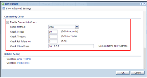
Place a check in the Enable Connectivity Check checkbox. Ensure that the Address is the remote GRE tunnel interface.

b. Add the second tunnel
IP Address: 10.10.0.2, Subnet Mask: 255.255.255.0
My Address: WAN2, Remote Gateway Address: 192.168.4.33

Place a check in the Enable Connectivity Check checkbox. Ensure that the Address is the remote GRE tunnel interface.

Step 2. Add a GRE tunnel trunk on USG1. Go to CONFIGURATION > Network > Interface > Trunk.
gre_trunk member:
tunnel0: Active
tunnel1: Passive

Step3. Add two IPSec VPN tunnels on USG1. Go to CONFIGURATION > VPN > IPSec VPN.
a. Add two VPN gateway policies.
First VPN Gateway policy (USG1 wan1 to USG2 wan1)
My Address: wan1, Peer Gateway Address: 192.168.3.33
Pre-Shared Key: 12345678
Secondary Gateway policy (USG1 wan2 to USG2 wan2)
My Address: wan2, Peer Gateway Address: 192.168.4.33
Pre-Shared Key: 12345678

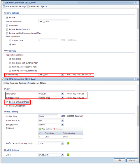
b. Add two VPN Connections
First VPN Connection
Enable Nailed-Up
Application Scenario: Site-to-Site
VPN Gateway: GRE0_GW
Local policy: 192.168.1.33
Remote policy: 192.168.3.33
Enable GRE over IPSec

Second VPN Connection
Enable Nailed-Up
Application Scenario: Site-to-Site
VPN Gateway: GRE1_GW
Local policy: 192.168.2.33
Remote policy: 192.168.4.33
Enable GRE over IPSec

Step 4. Add a policy routes on USG1. Go to CONFIGURATION> Network > Routing.
Source: LAN1_Subnet
Destination: Remote subnet
Next-Hop: gre_trunk
SNAT: none

Step5. Add two GRE tunnels on the USG2. Go to CONFIGURATION > Tunnel.
a. Add first tunnel
IP Address: 10.0.0.3, Subnet Mask: 255.255.255.0
My Address: WAN1, Remote Gateway Address: 192.168.1.33

Place a check in the Enable Connectivity Check checkbox. Ensure that the Address is the remote GRE tunnel interface.

b. Add Second tunnel
IP Address: 10.10.0.4, Subnet Mask: 255.255.255.0
My Address: WAN2, Remote Gateway Address: 192.168.2.33

Place a check in the Enable Connectivity Check checkbox. Ensure that the Address is the remote GRE tunnel interface.
Step6. Add a GRE tunnel trunk on USG2. Go to CONFIGURATION > Network > Interface > Trunk.
gre_trunk member:
tunnel0: Active
Tunnel1: Passive

Step 7. Add two IPSec VPN tunnels on USG2. Go to CONFIGURATION > VPN > IPSec VPN.
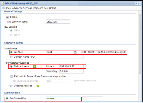
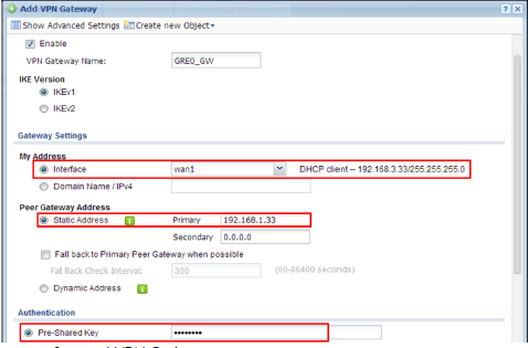
a. Add two VPN Gateways.
First VPN Gateway
My Address: wan1, Peer Gateway Address: 192.168.1.33
Pre-Shared Key: 12345678
Second VPN Gateway
My Address: wan2, Peer Gateway Address: 192.168.2.33
Pre-Shared Key: 12345678

b. Add two VPN Connections.
First VPN connection
Application Scenario: Site-to-Site
VPN Gateway: GRE0_GW
Local policy: 192.168.3.33
Remote policy: 192.168.1.33
Enable GRE over IPSec

Second VPN connection
Enable Nailed-Up
Application Scenario: Site-to-Site
VPN Gateway: GRE1_GW
Local policy: 192.168.4.33
Remote policy: 192.168.2.33
Enable GRE over IPSec
Step 8. Add a policy routes on USG2. Go to CONFIGURATION > Network > Routing.
Source: LAN1_Subnet
Destination: Remote subnet
Next-Hop: gre_trunk
SNAT: none

Categories
- All Categories
- 393 Beta Program
- 2.1K Nebula
- 116 Nebula Ideas
- 78 Nebula Status and Incidents
- 5.1K Security
- 51 USG FLEX H Series
- 247 Security Ideas
- 1.3K Switch
- 70 Switch Ideas
- 906 WirelessLAN
- 34 WLAN Ideas
- 5.9K Consumer Product
- 210 Service & License
- 332 News and Release
- 71 Security Advisories
- 21 Education Center
- 5 [Campaign] Zyxel Network Detective
- 1.9K FAQ
- 880 Nebula FAQ
- 415 Security FAQ
- 221 Switch FAQ
- 195 WirelessLAN FAQ
- 46 Consumer Product FAQ
- 137 Service & License FAQ
- 34 Documents
- 34 Nebula Monthly Express
- 72 About Community
- 63 Security Highlight